Pixelblaze Output Expander
GITHUB PROJECT: github.com/Pi4J/pi4j-jbang > PixelblazeOutputExpander.java
One of the most “fancy” electronic components is definitely a LED strip. It’s really cool to control a long strip of lights with only a few lines of code… But, there is a problem. The timing of the signals is crucial to reliably control these strips. Both Python and Java on a Raspberry Pi can struggle with these timings as they are running on Linux, a non-real-time operating system. So pauses in the garbage collection of the Java virtual machine, or any glitch in the operating system can cause unexpected effects on the LED strips. That’s why in most projects, a microcontroller (Arduino, Raspberry Pi Pico, ESP32,…) is used to drive the LED strip.
Full LED strip code walkthrough, and additional info in this live session with with Robert (aka Eitch) and Frank:
Intro
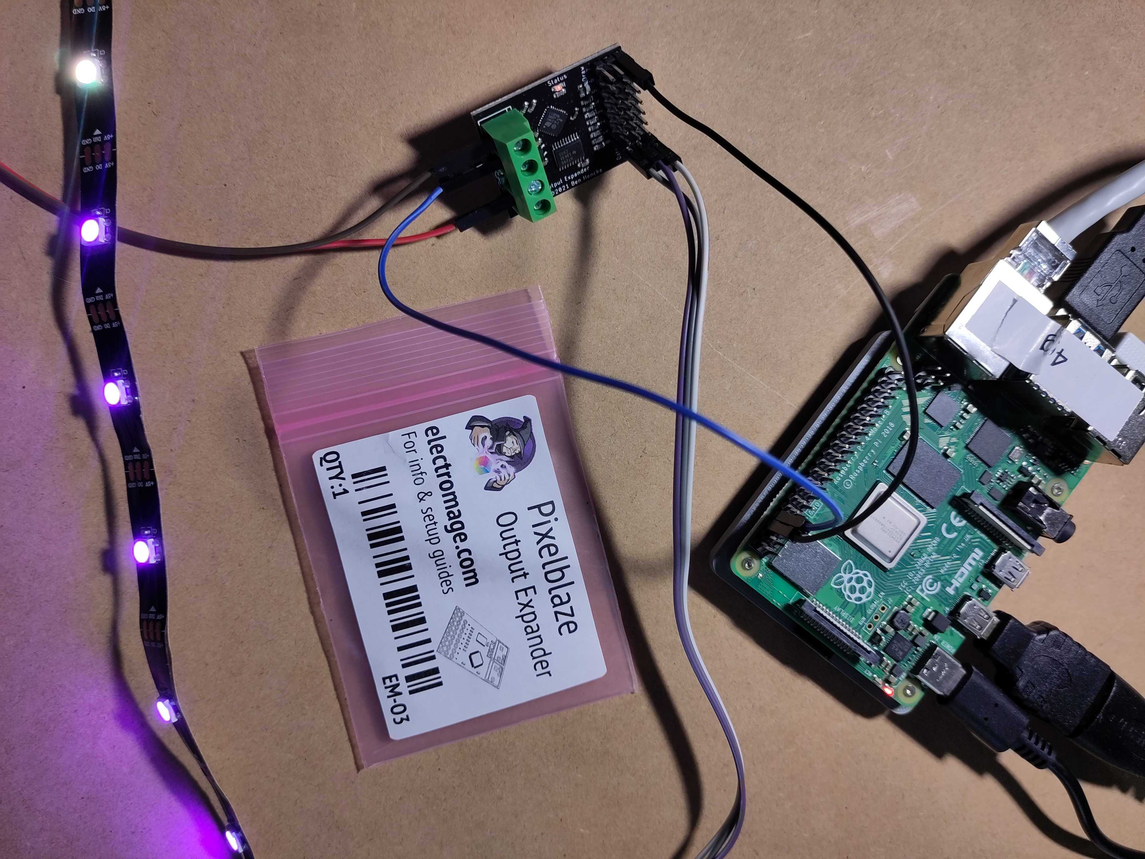
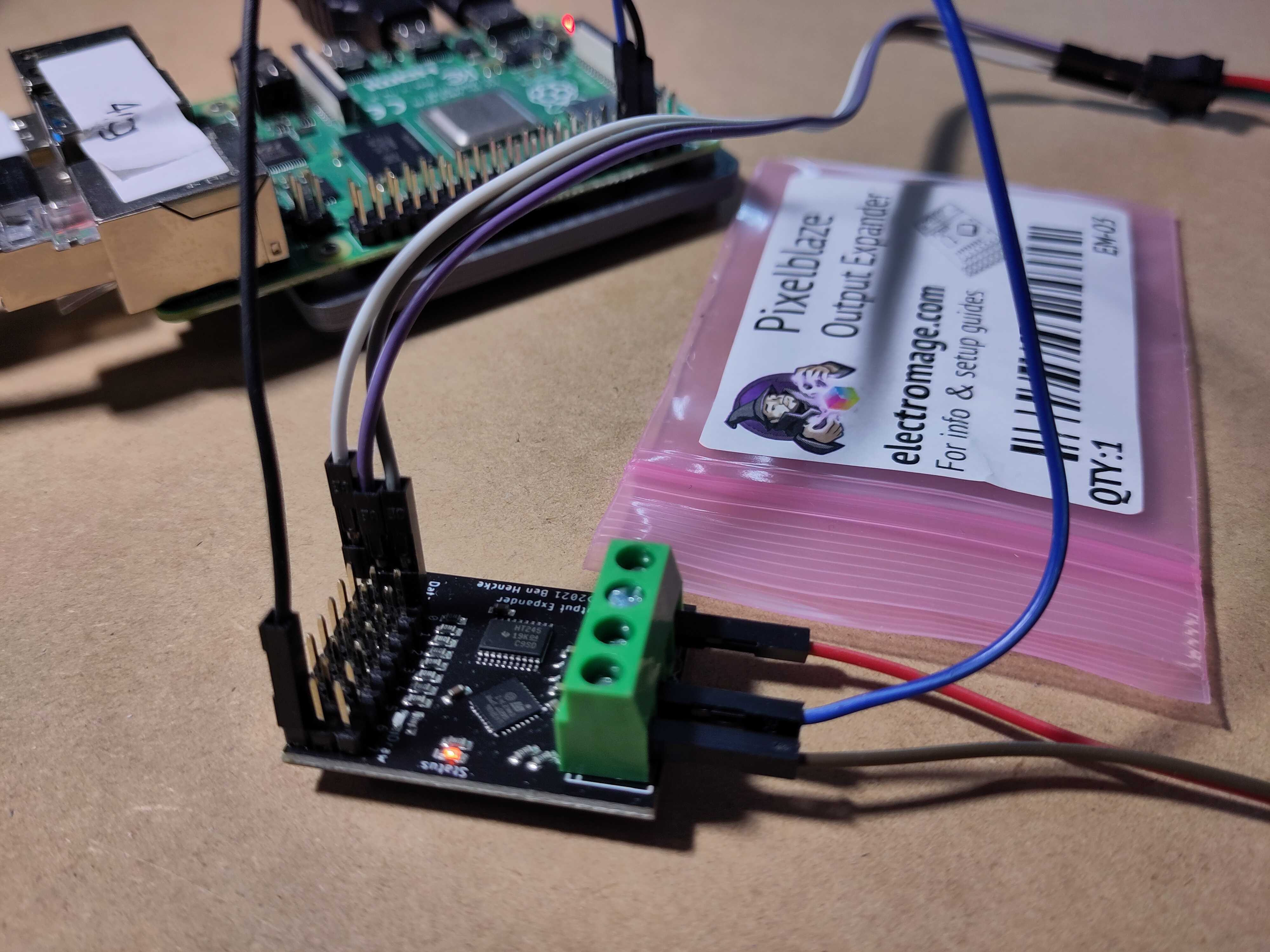
This example is using such approach with the Pixelblaze Output Expander (PBOE). This product was initially intended to connect more LED strips to the Pixelblaze V3 Standard - WiFi LED Controller and Pixelblaze V3 Pico - Tiny WiFi LED Controller. But because the expander is controlled through a serial connection, we can also use it with a Raspberry Pi.
You can buy this component here:
- Directly from the creator of the Pixelblaze in the US: ElectroMage.
- Outside of the US:
LED Strips
LED Strips Used in the Examples
The LED strips used in these examples, contain LEDs of the WS2812B type, which means they have SMD 5050-LEDs with an integrated IC-driver, so they can be addressed separately. A few examples:
How Data is Handled by LED Strips
To control such a LED strip, you need to send it a byte array with RGB (red/green/blue) values. Let’s use an example for a strip with three LEDs, on which you want to show:
- Full red (RGB #FF0000)
- Not full white (RGB #A6A6A6)
- Full blue (RGB #0000FF)
Although you may be used to use the color ordering RGB for e.g. CSS or in drawing applications, LED strips actually use GRB.
This means, we need a byte array with 9 values:
| Array index | 0 | 1 | 2 | 3 | 4 | 5 | 6 | 7 | 8 |
|---|---|---|---|---|---|---|---|---|---|
| LED | 1 | 2 | 3 | ||||||
| G, R, B | #00 | #FF | #00 | #A6 | #A6 | #A6 | #00 | #00 | #FF |
The IC of the first led will take the first 3 values from the byte array and output the remaining part to the second LED:
| Array index | 0 | 1 | 2 | 3 | 4 | 5 |
|---|---|---|---|---|---|---|
| LED | 2 | 3 | ||||
| G, R, B | #A6 | #A6 | #A6 | #00 | #00 | #FF |
Again, the second LED will take the first 3 values and output the remaining part:
| Array index | 0 | 1 | 2 |
|---|---|---|---|
| LED | 3 | ||
| G, R, B | #00 | #00 | #FF |
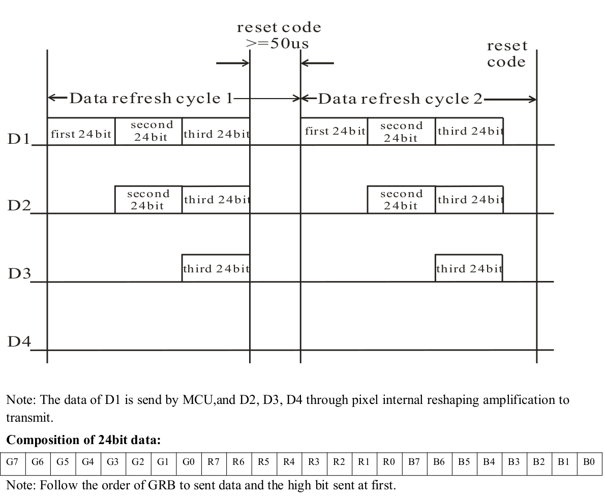
For this system to work correctly, a strict timing of the data signal is needed. Otherwise the IC will handle parts of the data as being a new package, and you’ll get unexpected results.
This is a timing diagram from a datasheet of WS2812B Intelligent control LED integrated light source:
Wiring
To control the PBOE, we actually only need one wire to be connected to the Raspberry Pi (RPi) for the serial data to be sent from RPi to PBOE. But we must not forget one important fact: a LED strip with a lot of LEDs will require more power than the RPi can supply. So we need an external power supply that is dimensioned correctly to provide all the power needed for the strip when all LEDs are at maximum level. As a guideline, 0,1W ~ 0,3W/LED is required per LED. For a strip with 60 LEDs/meter, that means 18W/meter, or a total of 90W for a 5-meter strip. That’s almost 20A at 5V!
Use an external power supply to power LED strips!!! The 5V of the Raspberry Pi is passed straight through from the USB and the current is therefore limited. Here is a good question with clear answers about this topic on StackExchange.
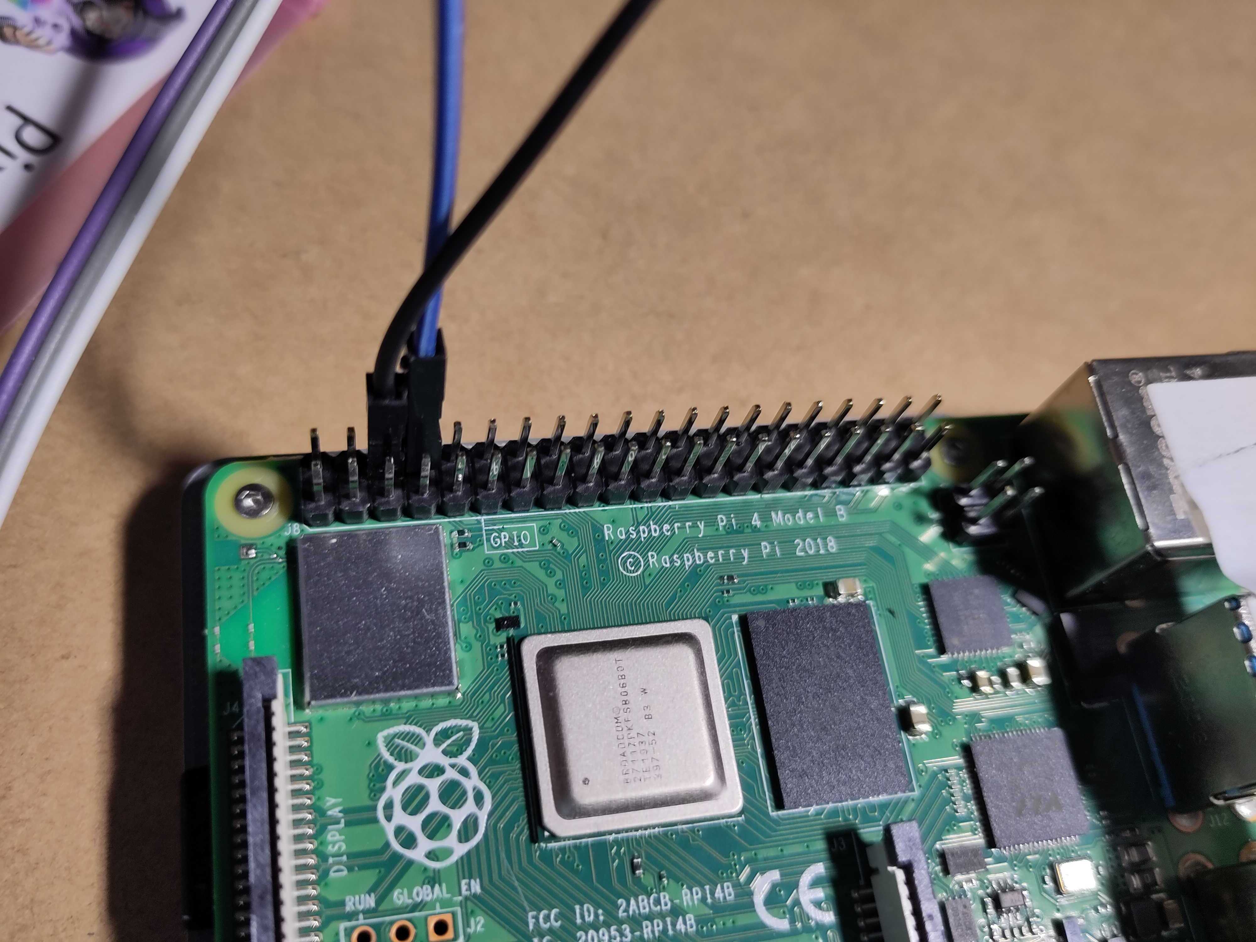
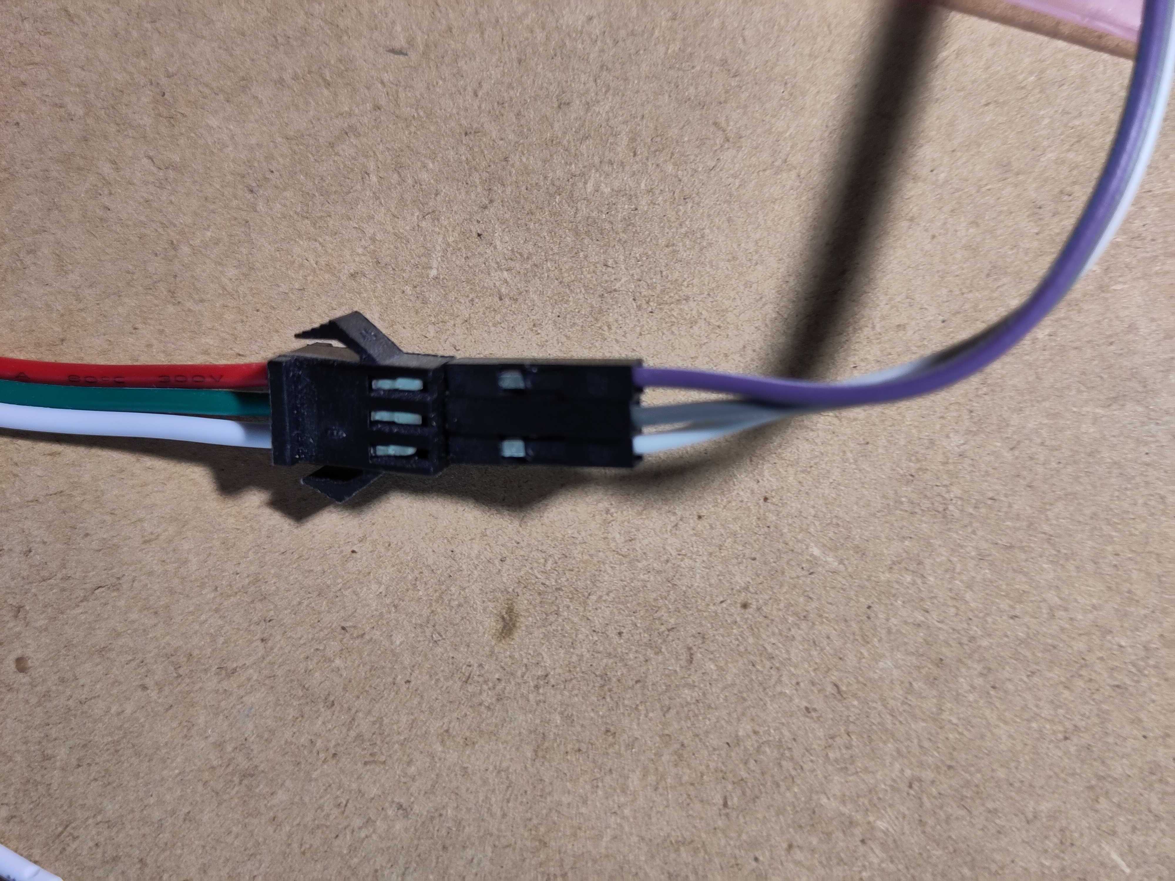
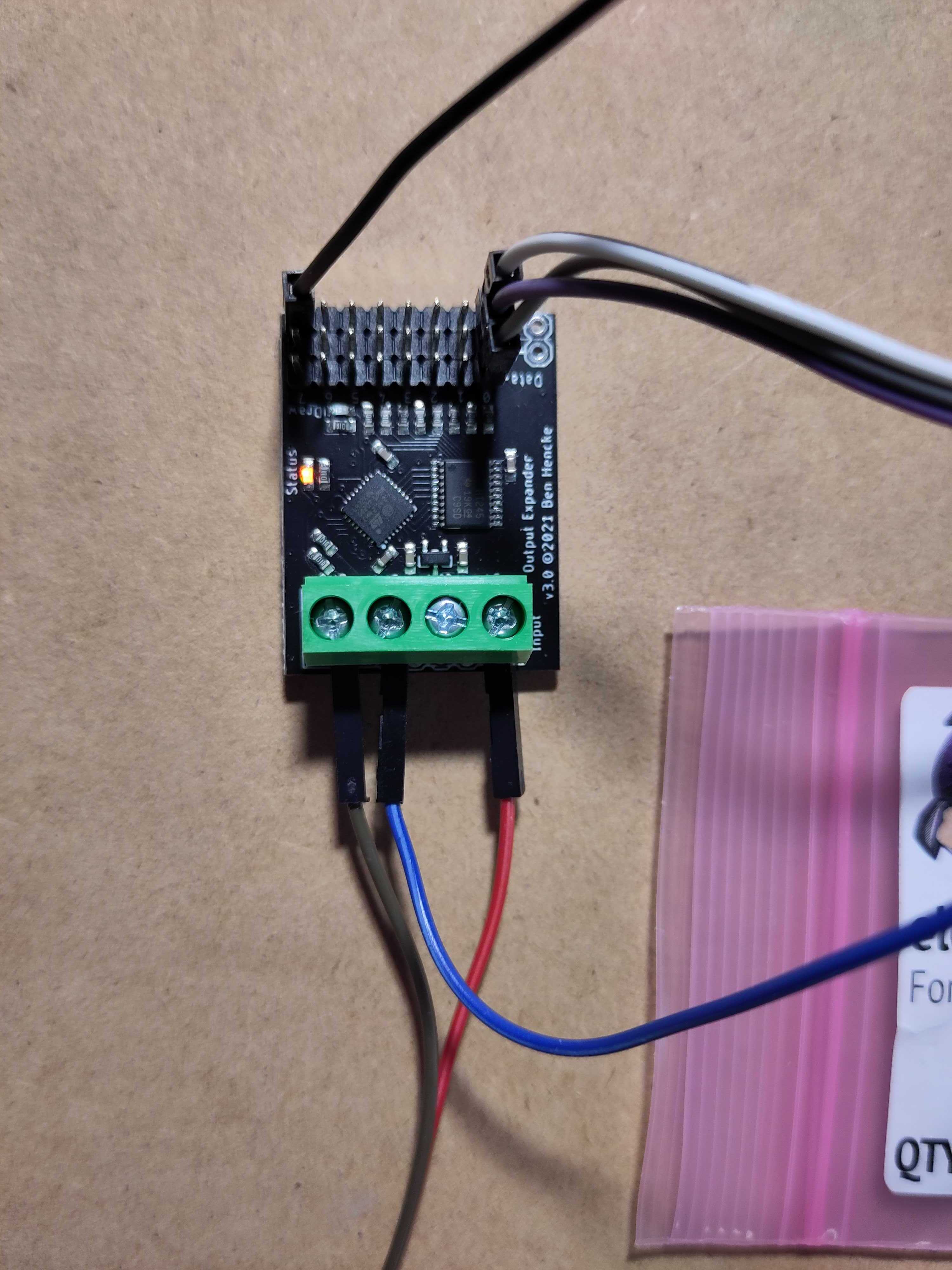
Connections between RPi, PBOE, and power supply:
- GND PBOE to GND power supply, common with GND of RPi
- 5V PBOE to external power supply
- DAT PBOE to BCM14 on Rpi (pin 8 = UART Tx)
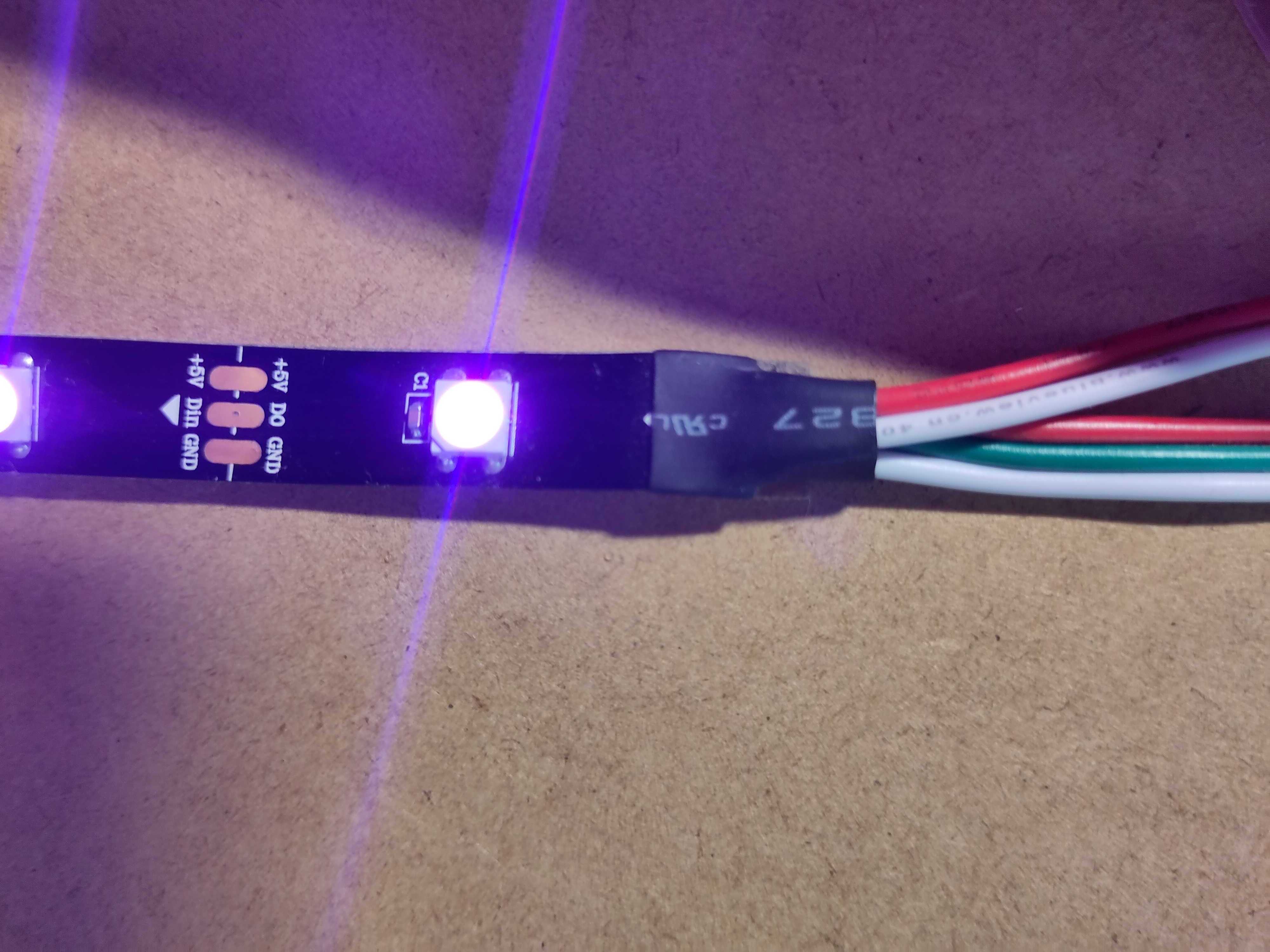
Connections between PBOE and LED strip:
- Din to PBOE Channel 0, Data
- 5V to PBOE Channel 0, 5V
- GND to PBOE Channel 0, GND
Enabling Serial
To be able to control the serial link from software, the following steps must be followed:
- In terminal:
sudo raspi-config - Go to “Interface Options”
- Go to “Serial Port”
- Select “No” for “login shell”
- Select “Yes” for “hardware enabled”
Status of the Pixelblaze Output Expander LEDs
- Fading / pulsing orange: Has not seen any valid looking data.
- Solid orange (for a short time): Received expander data.
- Green LED (for a short time): Received data for its channels and is drawing.
Application
Before proceeding with this example, make sure that you have a Raspberry Pi prepared to execute Java code with JBang as explained here.
Jeff Vyduna and Ben Hencke of ElectroMage, the creators of Pixelblaze, provided example Java code for this project. The serial data format is documented on GitHub. What the code is doing in short:
- Open serial communication to
/dev/ttyS0. - Use BaudRate
2000000, this is a hard requirement for the PBOE. - Send a byte array of RGB values for each LED.
- Send a
drawAllcommand to put the values on the LEDs. - Repeat as much as you want the two previous steps…
- Before the application stops, close the serial port.
helper.PixelBlazeOutputExpanderHelper
This example project doesn’t use the Pi4J serial communication (because it doesn’t support this baud rate - at this moment), but instead the com.fazecast:jSerialComm:2.10.2 library. Although we are using JBang and can execute the code with a single file, a separate file is used for the logic to interact with the PBOE, so it can be used in other examples.
Inside PixelBlazeOutputExpanderHelper, an inner class is used to set up the serial communication and provide a write method. This is the actual part of the code that is interacting with the PBOE via the serial port.
private class ExpanderDataWriteAdapter {

    private SerialPort port = null;
    private final String portPath;

    public ExpanderDataWriteAdapter (String portPath) {
        this.portPath = portPath;
        openPort();
    }

    private void openPort() {
        if (port != null) {
            System.out.println("Closing " + portPath);
            port.closePort();
        }
        try {
            port = null; //set to null in case getCommPort throws, port will remain null.
            port = SerialPort.getCommPort(this.portPath);
            port.setBaudRate(2000000);
            port.setComPortTimeouts(SerialPort.TIMEOUT_NONBLOCKING, 0, 0);
            port.openPort(0, 8192, 8192);
            System.out.println("Opening " + portPath);
        } catch (Exception e) {
            System.err.println("Could not open serial port " + e.getMessage());
        }
    }

    private void closePort() {
        if (port != null) {
            System.out.println("Closing " + portPath);
            port.closePort();
        }
    }

    public void write(byte[] data) {
        int lastErrorCode = port != null ? port.getLastErrorCode() : 0;
        boolean isOpen = port != null && port.isOpen();
        if (port == null || !isOpen || lastErrorCode != 0) {
            System.out.println("Port was open:" + isOpen + ", last error:" + lastErrorCode);
            openPort();
        }
        port.writeBytes(data, data.length);
    }
}
The remaining part of PixelBlazeOutputExpanderHelper exposes a few methods to write RGB values to the strip, or clear them all, but hides all the “internal logic” in private methods.
public class PixelBlazeOutputExpanderHelper {

    private static final byte CH_WS2812_DATA = 1;
    private static final byte CH_DRAW_ALL = 2;

    private final ExpanderDataWriteAdapter adapter;

    public PixelBlazeOutputExpanderHelper(String address) {
        System.out.println("Initializing serial");
        adapter = new ExpanderDataWriteAdapter(address);
    }

    public void sendAllOff(int channel, int numberOfLeds) {
        ...
    }

    public void sendColors(int channel, int bytesPerPixel, int rIndex, int gIndex, int bIndex, int wIndex, byte[] pixelData, boolean debug) {
       ...
    }

    public void closePort() {
        adapter.closePort();
    }

    private void sendDrawAll() {
        ...
    }

    private void writeCrc(CRC32 crc) {
        ...
    }

    private void packInt(byte[] outgoing, int index, int val) {
        ...
    }

    private ByteBuffer initHeaderBuffer(int size, byte channel, byte command) {
        ByteBuffer buffer = ByteBuffer.allocate(size);
        buffer.order(ByteOrder.LITTLE_ENDIAN);

        buffer.put((byte) 'U');
        buffer.put((byte) 'P');
        buffer.put((byte) 'X');
        buffer.put((byte) 'L');
        buffer.put(channel);
        buffer.put(command);
        return buffer;
    }

    private class ExpanderDataWriteAdapter {
        ...
    }
}
PixelblazeOutputExpander
Thanks to the helper-class, the code inside the actual demo is very small.
JBang Configuration and Imports
As with each JBang example, we need to define the first script line and the dependencies, one in this case, and we need to include the helper-source. Only two imports are needed for this example.
///usr/bin/env jbang "$0" "$@" ; exit $?

//DEPS com.fazecast:jSerialComm:2.10.2
//SOURCES helper/PixelBlazeOutputExpanderHelper.java

import helper.PixelBlazeOutputExpanderHelper;

import java.util.Random;
Initialize the Helper
The main method needs to initialize the helper and contains a helper method to send a specific color, one LED at a time, to a strip:
    private static PixelBlazeOutputExpanderHelper helper;

    public static void main(String[] args) throws InterruptedException {
        helper = new PixelBlazeOutputExpanderHelper("/dev/ttyS0");

        // RGB commands will be added here

        helper.closePort();
    }

    private static void sendOneByOne(int channel, int numberOfLeds, byte red, byte green, byte blue) throws InterruptedException {
        System.out.println("One by one on channel " + channel);
        for (int i = 0; i < numberOfLeds; i++) {
            byte[] oneLed = new byte[numberOfLeds * BYTES_PER_PIXEL];
            oneLed[i * BYTES_PER_PIXEL] = red;
            oneLed[(i * BYTES_PER_PIXEL) + 1] = green;
            oneLed[(i * BYTES_PER_PIXEL) + 2] = blue;
            helper.sendColors(channel, BYTES_PER_PIXEL, 1, 0, 2, 0, oneLed, false);
            Thread.sleep(50);
        }
    }
Controlling the LEDs
With all this code in place, we can start sending color data to the LED strip. The idea is to send a byte array containing a value for each color of the LEDs.
For instance, to send these colors to the first four LEDs, when using RGB-leds:
1 Red 2 Green 3 Blue 4 White
The byte array will look like this:
byte[] pixeldata = new byte[12]; // 3 colors * 4 leds

// Red = 0xff0000
byte[0] = (byte) 0xff;
byte[1] = (byte) 0x00;
byte[2] = (byte) 0x00;

// Green = 0x00ff00
byte[3] = (byte) 0x00;
byte[4] = (byte) 0xff;
byte[5] = (byte) 0x00;

// blue = 0x0000ff
byte[6] = (byte) 0x00;
byte[7] = (byte) 0x00;
byte[8] = (byte) 0xff;

// White = 0xffffff
byte[9] = (byte) 0xff;
byte[10] = (byte) 0xff;
byte[11] = (byte) 0xff;
Number of colors per LED
A LED on a strip can contain three inner LEDs for RGB, or four for RGBW. In case of RGBW, you need to adapt the script to define BYTES_PER_PIXEL = 4, and your byte array with the color values needs to include four values per LED.
// 3 colors per LED, White = 0xffffff
byte[0] = (byte) 0xff;
byte[1] = (byte) 0xff;
byte[2] = (byte) 0xff;

// 4 colors per LED, White = 0x000000ff
byte[0] = (byte) 0x00;
byte[1] = (byte) 0x00;
byte[2] = (byte) 0x00;
byte[3] = (byte) 0xff;
Order of the color values
Test the red, green, and blue output to define how the RGB colors are ordered in the PBOE controller and/or LED strip. You can define the relationship between the colors in your byte array with the actual led strip in the sendColors method, with the int rIndex, int gIndex, int bIndex, int wIndex parameters. If you are using RGB-leds and 3 bytes per pixel, the wIndex parameter is ignored.
Sending color values
The example code uses multiple byte arrays to send various colors and effects to a strip with 11 LEDs, connected to the channel 0 pins of the PBOE.
    private static final int BYTES_PER_PIXEL = 3;
    private static final int CHANNEL_STRIP_SHORT = 0;
    private static final int NUMBER_OF_LEDS_STRIP_SHORT = 11;

    public static void main(String[] args) throws InterruptedException{
        helper=new PixelBlazeOutputExpanderHelper("/dev/ttyS0");

        // All off on, short LED strip
        helper.sendAllOff(CHANNEL_STRIP_SHORT,NUMBER_OF_LEDS_STRIP_SHORT);
        Thread.sleep(500);

        // One by one red, short LED strip
        sendOneByOne(CHANNEL_STRIP_SHORT,NUMBER_OF_LEDS_STRIP_SHORT,(byte)0xff,(byte)0x00,(byte)0x00);

        // All the same color red, green, blue, short LED strip
        for(int color=0;color<BYTES_PER_PIXEL; color++){
            System.out.println("All "+(color==0?"red":(color==1?"green":"blue")));
            byte[]allSame=new byte[NUMBER_OF_LEDS_STRIP_SHORT*BYTES_PER_PIXEL];
            for(int i=0;i<NUMBER_OF_LEDS_STRIP_SHORT; i++){
                allSame[(BYTES_PER_PIXEL*i)+color]=(byte)0xff;
            }
            helper.sendColors(CHANNEL_STRIP_SHORT,BYTES_PER_PIXEL,1,0,2,0,allSame,false);

            Thread.sleep(1000);
        }

        // Fill strip with random colors, short LED strip
        Random rd=new Random();
        for(int i=0;i< 5;i++){
            System.out.println("Random colors "+(i+1));
            byte[]random=new byte[NUMBER_OF_LEDS_STRIP_SHORT*BYTES_PER_PIXEL];
            rd.nextBytes(random);
            helper.sendColors(CHANNEL_STRIP_SHORT,BYTES_PER_PIXEL,1,0,2,0,random,false);
            Thread.sleep(1000);
        }

        // Red alert, short LED strip
        byte[]red=new byte[NUMBER_OF_LEDS_STRIP_SHORT*BYTES_PER_PIXEL];
        int i;
        for(i=0;i<NUMBER_OF_LEDS_STRIP_SHORT; i++){
            red[i*BYTES_PER_PIXEL]=(byte)0xff;
        }
        for(i=0;i< 5;i++){
            System.out.println("All red");
            helper.sendColors(CHANNEL_STRIP_SHORT,BYTES_PER_PIXEL,1,0,2,0,red,false);
            Thread.sleep(100);
            helper.sendAllOff(CHANNEL_STRIP_SHORT,NUMBER_OF_LEDS_STRIP_SHORT);
            Thread.sleep(100);
        }
}
The example application also contains demos for a longer strip with 300 LEDs (5 meter) and a 8*32 matrix, connected to the second (index 1) and third channel (index 2).
    private static final int CHANNEL_STRIP_LONG = 1;
    private static final int CHANNEL_MATRIX = 2;
    private static final int NUMBER_OF_LEDS_STRIP_LONG = 300;
    private static final int NUMBER_OF_LEDS_MATRIX = 256; // 8*32

    // One by one red/green/blue on long strip, 5 meter with 60 LEDs/meter
    sendOneByOne(CHANNEL_STRIP_LONG, NUMBER_OF_LEDS_STRIP_LONG, (byte) 0xff, (byte) 0x00, (byte) 0x00);
    sendOneByOne(CHANNEL_STRIP_LONG, NUMBER_OF_LEDS_STRIP_LONG, (byte) 0x00, (byte) 0xff, (byte) 0x00);
    sendOneByOne(CHANNEL_STRIP_LONG, NUMBER_OF_LEDS_STRIP_LONG, (byte) 0x00, (byte) 0x00, (byte) 0xff);

    // Flash all red/white on long strip 1, 5 meter with 60 LEDs/meter
    byte[] fiveMeterRed = new byte[NUMBER_OF_LEDS_STRIP_LONG * BYTES_PER_PIXEL];
    byte[] fiveMeterWhite = new byte[NUMBER_OF_LEDS_STRIP_LONG * BYTES_PER_PIXEL];
    for (i = 0; i < NUMBER_OF_LEDS_STRIP_LONG; i++) {
        fiveMeterRed[i*BYTES_PER_PIXEL]= (byte) 0xff;
        fiveMeterWhite[i*BYTES_PER_PIXEL]= (byte) 0xff;
        fiveMeterWhite[(i*BYTES_PER_PIXEL) + 1]= (byte) 0xff;
        fiveMeterWhite[(i*BYTES_PER_PIXEL) + 2]= (byte) 0xff;
    }
    for (i = 0; i < 5; i++) {
        System.out.println("All RED on LED strip on channel 1");
        helper.sendColors(CHANNEL_STRIP_LONG, BYTES_PER_PIXEL, 1, 0, 2, 0, fiveMeterRed, false);
        Thread.sleep(500);
        System.out.println("All RED on LED strip on channel 1");
        helper.sendColors(CHANNEL_STRIP_LONG, BYTES_PER_PIXEL, 1, 0, 2, 0, fiveMeterWhite, false);
        Thread.sleep(500);
    }

    // All off, long LED strip
    helper.sendAllOff(CHANNEL_STRIP_LONG, NUMBER_OF_LEDS_STRIP_LONG);
    Thread.sleep(100);

    // All red, 8*32 LED matrix
    byte[] redMatrix = new byte[NUMBER_OF_LEDS_MATRIX * BYTES_PER_PIXEL];
    for (i = 0; i < NUMBER_OF_LEDS_MATRIX; i++) {
        redMatrix[i*BYTES_PER_PIXEL]= (byte) 0xff;
    }
    for (i = 0; i < 5; i++) {
        System.out.println("All red on LED matrix on channel 2");
        helper.sendColors(CHANNEL_MATRIX, BYTES_PER_PIXEL, 1, 0, 2, 0, redMatrix, false);
        Thread.sleep(100);
        helper.sendAllOff(CHANNEL_MATRIX, NUMBER_OF_LEDS_MATRIX);
        Thread.sleep(100);
    }
Running the Application
No sudo is needed for serial communication with the jSerialComm library, so the application can be started with:
$ jbang PixelblazeOutputExpander.java
Initializing serial
Opening /dev/ttyS0
All off on channel 0 with 11
All off on channel 1 with 300
All off on channel 2 with 256
One by one on channel 0, will take 2s
All red
All green
All blue
Random colors 1
..
All red
All off on channel 0 with 11
...
One by one on channel 1, will take 6s
...
All red on LED strip on channel 1
All off on channel 1 with 300
All red on LED matrix on channel 2
...
Closing /dev/ttyS0
Conclusion
I’m still curious to see the reliability of this serial control for LED strips in combination with other loads on the Raspberry Pi, but the Pixelblaze Output Expander is a great way to easily control such strips!